
ElectroMagnetic induction
(1) Introduction
(1) Introduction
- While studying magnetism we learned that electricty and magnetism are interrelated and infact moving charges or electric currents produces magnetic field that can deflect magnetic compass needle
- A question arises,can moving magnetic field produce electricty .Answer is yes and it was first showed by a british scientist Michael faraday in 1931 who after performing various experiments found that moving magnetic field can give rise to the EMF
- Independently the effect was discovered by Joseph Henry in USA at about the same time
- In this chapter we will discuss about the electric and magnetic field changing with time
- More precisely we will consider the phenomenon related to time changing current or time changing magnetic fields
- faraday in 1831 first discovered that whenever the number it of magnetic lines of forces in a circuit changes ,a emf is produced in the circuit and is known as induced emf and this phenomenon is known as Electro Magnetic Induction
- If the circuit is closed one then a current flows through it which is known an induced current
- This induced emf and current lasts only for the time while magnetic flux is chnaging
- We now illustrate two examples of the sort that faraday and henry performed
- Figure below shows a closed circuit containing coil of insulated wire.
- Also note that circuit does not contain any source of emf so there is no deflection in the galvanometer
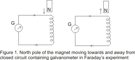
- If we move bar magnet towards the coil keeping the coil stationary with north pole of the magnet facing the coil (say) then we notice deflection in needle of the galvanometer indicating the pressence of the current in the circuit
- This deflection observed is only for the time interval during which the magnet is in motion
- Now if we begin to move the magnet in the opposite direction then the galvanometer needle is now deflected in the opposite direction
- again if we move the magnet towards the coil ,with its south pole facing the coil,the deflection is now in opposite direction,again indicating that the current now setup in the coil is in reverse direction to that when the north pole faces the wire
- A deflection is also oberved in galvanometer when the magnet is held stationary and circuit is moved away from the magnet.
- It is further observed that faster is the motion of magnet ,larger is the deflection in the galavanometer needle.
- From this experiment faraday convinced that magnet moving towards the coil one way has the same effect moving coil towards the magnet the other way.
- Figure-2 given below shows a primary coil P connected to the battery and a secondary coild connected to the galvanometer
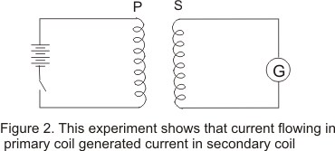
- Now we have replaced magnet of the previous experiment with a current carrying coil and expect to observe similar effect as current carrying coil produces magnetic field.
- The motion of either of the coils shows deflection in the galvanometer.
- Also galvanemter shows a sudden deflection in one direction when current was started in primary coil and in the opposite direction when the current was stopped.
(3) Magnetic Flux
- The flux of magnetic field through a surface is defined in a similar manner as we defined flux in the electric field
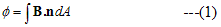
- if dA be an area element on any arbitrary surface and n be the unit vector perpendicular to the area element then magnetic flux is defined as
- If the surface under considerations is a plane of area A and magnetic field is constant in both the magnitude and direction over the surface and θ is the angle between magnetic field B and unit normal to the surface then magnetic flux is given by
Φ=BAcosθ --(2) - Unit of flux is Wb(weber)
1Wb=1T.m2
- From experiments on EM induction, faraday came to conclude then an emf was being induced in the coil when the magnetic flux linked to it was being changed either by
(i) Moving magnet close or away from the coil(experiment 1)
(ii) Chnaging amouny of current in the primary coil or motion of either of the coils relative to each other (experiment 2) - From these observations faraday enunciated an important law. The magitude of the induced emf produced in the coil is given by
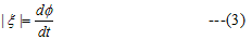
where Φ is the magnetic flux as given by equation (1) .ξ is expressed in volts - If the circuit is a tightly wound coil of N turns then total flux linked by N turns coil is NΦ.So induced EMF is whole coil is
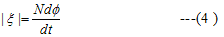
Above equation only give the magnitude of the induced EMF and it does not give its direction. - we know that unit of magnetic flux is 1 weber=1 T.m2
- If magnetic flux linking a single turn changes at a rate of 1weber per second then Induced emf=Magnetic flux/time=1 weber/sec Now since weber=Nm/Amp
Hence 1 weber/sec= 1 N.m/A.s =1 Joule/coulumb - Hence the unit of emf is volt.
- The direction of induced current and emf is given by lenz's law
- Due to change in magnetic flux through a closed loop an induced current is established in the loop
- Lenz's law states that
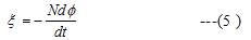
'The induced current due to the induced emf always flow in such a direction as to oppose the change causing it' - Now we can combine faraday's law as given in equation (4) to find the direction of emf
- Thus we can say that "The emf induced in a coil is equal to the negative rate of the change of the magnetic flux linked with it "
- To explain this law again consider faradays experiment 1 in which north pole of the magnet moves towards a closed coil
- This movement of north pole of magnetic induces current in the coil in such a direction so that end of the coil ,facing and approaching north pole becomes a magnetic north pole
- The repulsion between two poles opposes the motion of the magnet towards the coil
- Thus work has to be done to push the magnet against the coil
- It is this mechanical work which causes the current to flow in the coil against its resistance R and supply the energy for the heat loss
- The mechanical workdone is converted to electrical energy which produces the heat energy
- If the direction of the induced current were such as not to oppsose the motion ,then we would be obtaining electrical energy continously without doing any work ,which is impossible
- So ,every things seems to be all right if we accept lenz's law otherwise the principle of conservation of the energy would be voilated
- Direction of the induced current can be found using Fleming right hand rule.
" If we stretch thumb ,index and middle finger perpendicular to one another then index fingers points in direction of the magnetic field ,middle finger in direction of induced current and thum points in direction of the motion of the conducter"
(6) Motional EMF
- We know that an emf is produced in the loop when the amount of magnetic flux linked with the circuit os changed.
- The flux Φ linked with the loop can be changed by
(i) Keeping the loop at rest and changing the magnetic field i.e , there is no physical movemnt of either the source of emf or the loop(or coil) through which the magnetic flux is linked but the magnetic field changes with time and this may caused by changing the electric current producing the field
(ii)Keeping the magnetic field constant and moving the loop or source of the magnetic field partly or wholey i.e the change is produced by the relative motion of the source of the magnetic field and the lopp (or coil) through which the magnetic field passes. - In both the cases of producing the emf,the induced emf is given by the same law i.e it is equal to the time rate of change of the magnetic flux.
- In the later case emf induced due to the relative motion of source of magnetic field and coil is called motional emf.
- This phenomemon of motionla emf can be understood easily in lorentz force on moving charges
- Consider a thin conducting rod AB length l moving in the magnetic field B with constant velocity v as shown in the below in the figure
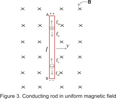
- This uniform magnetic field B is perpendicular to the plane of the diagram ,directed away from the reader
- Rod is moving in the magnetic field in such a way that its velocity is perpendicular to the magnetic field B and its own axis
- when we move conducting rod AB with velocity v,free electrons in it gain velocity in the direction of the motion and in the presence of magnetic field ,these free electrons experiences lorentz force perpendicular to both B and v
- The electrons under this force accumulate at end end ,providing it negative polarity and the other end deprived of the electrons becomes positively charged
- Magnetic force or lorentz force Fm acting on these moving electrons is Fm=qv X B
where q=-1.6*10-19 C ,charge on each electron - According to fleming left hand rule force on negative charges is towards B hence negative charge accumulates at B and positive charge appears at A
- As charges accumulates at the ends of the rod,an electric field E is produced in the rod from A to B.This field E is of non electrostatics origins and is produced by the changing magnetic fields
- This electric field in turns produces a force on electron in the conducting rod which is opposite to the lorentz force so
Fe=qE - when enough charge accumulates a situation comes when this electric force cancels out lorentz force and then free electrons do not drift anymore.In this situation
Fm =Fe or |qv X B |=|qE| or vB=E - In this situation there is no force acting on the free electrons of the rod AB. Potential difference between the ends A and B of the rod would be
V=El=vBl This is the emf induced in the rod AB due to its motion in the magnetic field - Thus motional emf induced in the rod moving in magnetic field is ξ=vBl ----(6)
- If the velocity v of the rod makes an angle θ with the direction of the magnetic field ,the potential difference induced between the ends of the conductor will be
ξ=vBlsinθ
as vsinθ is the component of v perpendicular to B - If the rod moves parallel to the field i.e, θ =0 no potential difference will be induced
- The emf associated with the moving rod in Figure 3 is analogous to that of a battery with the positive terminal at A and negative terminal at B
- If ends of A and B are connected by an external resistor and if r is the internal resistance of the rod then
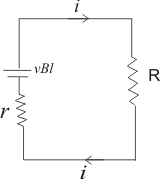
an electric field is produced in this resitor due to the potential differebce and a current is established in the circuit with direction from A to B in the external circuit - Since magnitude of current of induced emf is
ξ=vBl
So current is,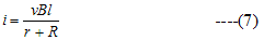
and direction of current can be found using lenz's law - We now know the current flowing in the circuit from this we can calculate the power loss and force F connected with this motion Thus
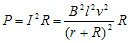
if r <<< R then it can be neglected so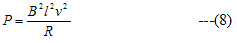
and Force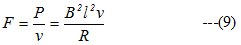
(7) Induced Electric Fields
- In the earliar section we have studied that when a conductor moves in a magnetic field induced current is generated
- Now consider a situation in which conductor is fixed in a time varying magnetic field .In this situation magnetic flux through the conducting loop changes with time and an induced current is generated
- Figure below shows a soleniod encirceled by a conducting loop with a small galvanometer
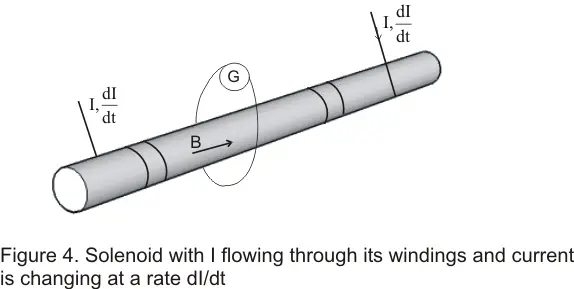
- Current I through the soleniod sets up a magnetic field B along its axis and a magnetic flux Φ passes through the surface bounded by the loop
- Now when the current I through the soleniod changes ,the galvanometer deflects for the time during which the flux is changing .This indicates that an emf is induced in the conductor.
- From Faraday's law this emf is given by the relation eq Here as we earliar stated that the conductor is sationary and the flux through the loop is chnaging due to the magnetic field varying on time
- Since charges are at rest (v=0) so magnetic forces Fm=q(v X B) cannot set the charges to motion.Hence induced current in the loop appears becuase of the presence of an electric field E in the loop
- It is this electric field E which is responsible for the induced emf and hence for the current flowing in a fixed loop placed in a magnetic field varying with time
- This electric field produced here is purely a field of nonaelectrostatic origin i.e it originated due to the magnetic field varying with time, and induced emf may be defined as the line integral of this non-electrostatic field .Thus,

- Using faraday law
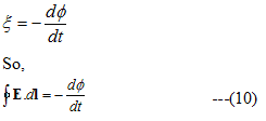
- From equation (10) we see that line intregal of electric field induced by varying magnetic field differs from zero.This means we can not define a electrostatic potential corresponding to this field.
- Hence this electric field produced by changing electric field is non-electrostatis and non-conservative in nature.
- We call such a field as induced electric field.
No comments:
Post a Comment