
Alternating current
(1) Introduction
(1) Introduction
- We have already discussed about direct current (DC) which is produced by the voltage source whose pole does not change their polarity with time
- Hence direction of flow of direct current does not changes with time
- Alternating current on the other hand is produced by voltage source whose terminal polarity keeps alternating with time i.e. terminal which was positive at one instant of time becomes negative some time later and vice -versa
- Due to changing polarity of voltage source direction of flow of current also keep changing
- In this chapter we would learn how voltage and current changing with time are related to each other in various circuits with components namely resistors, capacitor and inductor.
- An alternating current is one whose magnitude changes sinusoidal with time .Thus alternating current is given by

Where
i0=current amplitude or peak value of alternating current
If T is the time period of alternating current and f is the frequency, then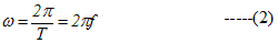
Where ω is called angular frequency of A.C and φ is known as phase constant - Instead of sine function AC can also be represented by cosine function and both representation leads to same results. We will discuss circuits with sine representation of A.C
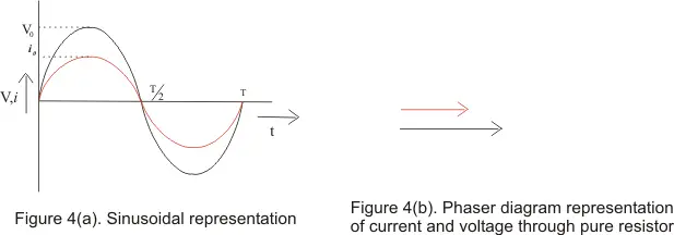
- Figure below shows the variation of A.C with time
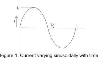
- Complete set of variations of the current in one time period T is called cycle
- The emf or voltage whose magnitude changes sinusoidal with time is known as alternating emf and is represented by

where V0 is the peak value of alternating current.
- When an alternating current passed through a moving coil galvanometer it shows no deflection ,this is because for one complete cycle mean value of alternating current is zero as AC flows in one direction during one half cycle and in opposite direction during another half cycle.
- But mean value of A.C is finite over half cycle.
- So, mean or average value of AC is defined either for positive half cycle or for negative half cycle
- So,
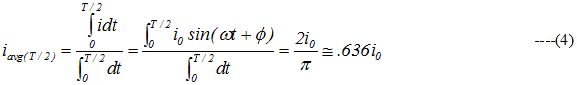
- From equation (4),we see that the average value of A.C during the half cycle is .636 times or 63.6% of its peak value
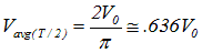
- Similarly we can show that
- During next half cycle mean value of ac will be equal in magnitude but opposite in direction.
- Always remember that mean value of AC over a complete cycle is zero and is defined over a half cycle of AC.
(4) Root Mean square value of AC
(5) Phasor diagram
(6) A.C through pure resistor
- We know that time average value of AC over one cycle is zero and it can be proved easily
- Instantaneous current I and time average of AC over half cycle could be positive for one half cycle and negative for another half cycle but quantity i2 would always remain positive
- So time average of quantity i2 is
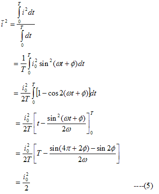
This is known as the mean square current - The square root of mean square current is called root mean square current or rms current.
Thus,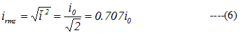
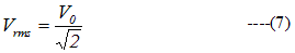
thus ,the rms value of AC is .707i0 of the peak value of alternating current - Similarly rms value of alternating voltage or emf is
- If we allow the AC current represented by i=i0sin(ωt+φ) to pass through a resistor of resistance R,the power dissipated due to flow of current would be
P=i2R - Since magnitude of current changes with time ,the power dissipation in circuit also changes
- The average Power dissipated over one complete current cycle would be

If we pass direct current of magnitude irms through the resistor ,the power dissipate or rate of production of heat in this case would be
P=(irms)2R - Thus rms value of AC is that value of steady current which would dissipate the same amount of power in a given resistance in a given tine as would gave been dissipated by alternating current
- This is why rms value of AC is also known as virtual value of current
(5) Phasor diagram
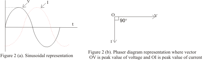
- Phasor diagrams are diagram representing alternating current and voltage of same frequency as vectors or phasors with the phase angle between them
- Phasors are the arrows rotating in the anti-clockwise direction i.e. they are rotating vectors but they represents scalar quantities
- Thus a sinusoidal alternating current and voltage can be represented by anticlockwise rotating vectors if they satisfy following conditions
- Length of the vector must be equal to the peak value of alternating voltage or current
- Vector representing alternating current and voltage would be at horizontal position at the instant when alternating quantity is zero
- In certain circuits when current reaches its maximum value after emf becomes maximum then current is said to lag behind emf
- When current reaches its maximum value before emf reaches its maximum then current is said to lead the emf
- Figure below shows the current lagging behind the emf by 900
(6) A.C through pure resistor
- Figure below shows the circuit containing alternating voltage source V=V0sinω connected to a resistor of resistance R
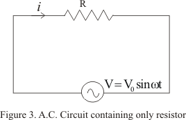
- Let at any instant of time ,i is the current in the circuit ,then from Kirchhoff’s loop rule
V0sinωtRi
or
i=(V0/R)sinωt
=i0sinωt ----(8)
Where,
i0=V0/R ----(9) - From instantaneous values of alternating voltage and current ,we can conclude that in pure resistor ,the current is always in phase with applied voltage
- Their relationship is graphically represented as
No comments:
Post a Comment