
Diffraction and polarization of light
9)Law of Malus
1. Introduction
- It is a common observation with the waves of all kind that they bend round the edge of an obstacle
- Light like other waves also bends round corners but in comparison to sound waves small bending of light is due to very short wavelength of light which is of the order of 10-5
- This effect of bending of beams round the corner was first discovered by grimed (Italy 1618-1663)
- We now define diffraction of light as the phenomenon of bending of light waves around the corners and their spreading into the geometrical shadows
- Fresnel then explained that the diffraction phenomenon was the result of mutual interference between the secondary wavelets from the same dif wave front
- Thus we can explain diffraction phenomenon using Huygens’s principle
- The diffraction phenomenon are usually divided into two classes
i) Fresnel class of diffraction phenomenon where the source of light and screen are in general at a finite distance from the diffracting aperture
ii) Fruanhofer class of diffraction phenomenon where the source and the screen are at infinite distance from the aperture, this is easily achieved by placing the source on the focal plane of a convex lens and placing screen on focal plane of another convex lens. This class of diffraction is simple to treat and easy to observe in practice - Here in this chapter we will only be considering fraunhofer class diffraction by a single slit
- Let us first consider a parallel beam of light incident normally on a slit AB of width 'a' which is of order of the wavelength of light as shown below in the figure
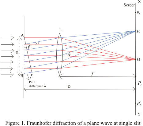
- A real image of diffraction pattern is formed on the screen with the help of converging lens placed in the path of the diffracted beam
- All the rays that starts from slit AB in the same phase reinforce each other and produce brightness at point O on the axis of slit as they arrive there in the same phase
- The intensity of diffracted beam will be different in different directions and there are some directories where there is no light
- Thus diffraction pattern on screen consists of a central bright band and alternate dark and bright bands of decreasing intensity on both sides
- Now consider a plane wave front PQ incident on the narrow slit AB. According to Huygens principle each point t on unblocked portion of wavefront PQ sends out secondary wavelets in all directions
- Their combined effect at any distant point can be found y summing the numerous waves arriving there from the principle of superposition
- Let C be the center of the slit AB.The secondary waves, from points equidistant from center C of the clit lying on portion CA and CB of wave front travel the same distance in reaching O and hence the path difference between them is zero
- These waves reinforce each other and give rise to the central maximum at point O
- We now consider the intensity at point P1 above O on the screen where another set of rays diffracted at a angle θ have been bought to focus by the lens and contributions from different elements of the slits do not arise in phase at P1
- If we drop a perpendicular from point A to the diffracted ray from B,then AE as shown in figure constitutes the diffracted wavefront and BE is the path difference between the rays from the two edges A and B of the slit.
- Let us imagine this path difference to be equal to one wavelength.
- The wavelets from different parts of the slit do not reach point P1 in the phase because they cover unequal distance in reaching P1.Thus they would interfere and cancel out each other effect. For this to occur
BE=λ
Since BE=ABsinθ
asinθ=λ
or sinθ=λ/a
or θ=λ/a ---(1)
As angle of diffraction is usually very small so that
sinθ=θ - Such a point on screen as given by the equation (1) would be point of secondary minimum
- It is because we have assume the slit to be divided into two parts, then wavelets from the corresponding points of the two halves of the slit will have path difference of #955;/2 and wavelets from two halves will reach point P1 on the screen in a opposite phase to produce minima
- Again consider the point P2 in the figure 1 and if for this point path difference BE=2λ ,then we can imagine slit to be divided into four equal parts
- The wavelets from the corresponding points of the two adjacent parts of the slit will have a path difference of λ/2 and will mutually interfere to cancel out each other
- Thus a second minimum occurs at P2 in direction of θ given by
θ=2θ/a - Similarly nth minimum at point Pn occurs in direction of θ given by
θn=nθ/a ---(2)
- If there is any point on the screen for which path difference
BN=asinθ=3θ/2
Then point will be position of first secondary maxima - Here we imagine unblocked wavefront to be divided into three equal parts where the wavelets from the first two parts reach point P in opposite phase thereby cancelling the e effects of each other
- The secondary waves from third part remain uncancelled and produce first maximum at the given point
- we will get second secondary maximum for BN=5θ/2 and nth secondary maxima for
BN=(2n+1)θ/2 =asinθn ---(3)
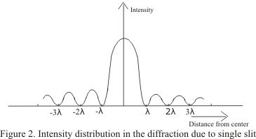
where n=1,2,3,4.. - Intensity of these secondary maxima is much less then central maxima and falls off rapidly as move outwards
- Figure below shows the variation of the intensity distribution with their distance from the center of the central maxima
3) Resolving power
- When two objects are very close to each other they may appear as one and we might not see them as separate objects just by magnifying them
- To separate two objects which are very close together, optical instrument such as telescope ,microscope,prism,grating etc are employed
- The separation of such close object is termed as resolution and the ability of an optical instrument to produce distinctly separate images of two close objects is called its resolving power
- Every optical instrument has a limit up to which it can produce distinctly separate images to two objects placed very close to each other
- After detailed study of the intensity of diffraction pattern of two very close point objects ,lord Rayleigh suggested that the two objects will be just resolved when central maximum of diffraction pattern of first object lies on first secondary minimum of diffraction pattern of second object
- The minimum distance between two point object which can just appear to be as separate by optical instrument is called the limit of resolution of the instrument
- we will discuss about the resolving power of optical instrument when we study exclusively about optical instruments
- Waves are generally of two types
i) Longitudinal waves: In case of longitudinal waves ,particles of the medium oscillates along the direction of the propagation of the waves
ii) Transverse waves: In this case direction of oscillation of particles is perpendicular to the direction of propagation of waves - we already know that light is an EM wave in which electric and magnetic field vector vary sinosoidally,perpendicular to each other as well as perpendicular to the direction of propagation of light wave
- This shows that light waves consists of transverse waves
- The fact that light consists of transverse waves can be confirmed in the experiments in which beams of lights were allowed to pass through Polaroid which are artificial crystalline materials that allow lights vibrations to pass through only in a particular plane
- We would now observe the light passing through two Polaroid A and B placed one behind another in from of source of light as shown below in the figure
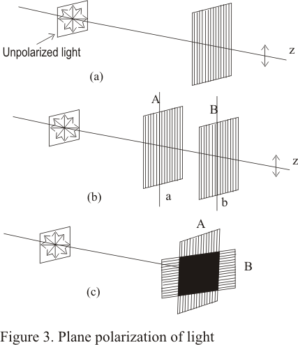
- when axes a and b of Polaroid A and B respectively are parallel to each other then the light through Polaroid B appears slightly darker intensity of light is reduced after being transmitted from Polaroid A
- Since axis of both the Polaroid are parallel to each other so light transmitted from Polaroid A is transmitted as it is by Polaroid B
- Now if start rotating Polaroid B about the z-axis ,one will observe the variation of intensity i.e. light passing through crystal B becomes darker and darker and disappears at one stage
- This happens when axis a of Polaroid A is perpendicular to axis b of the Polaroid B as shown in fig 3(b)
- Again on rotating Polaroid B in same direction light reappears and becomes brightest when the axis a and b are again parallel
- This simple experiment proves that light consists of transverse waves
- Here in this experiment Polaroid A acts as polarizer and the beam transmitted through polarizer is linearly polarized and second Polaroid acts as analyzer
5) Vibrations in unpolarized and polarized light
- A light wave is a transverse wave having vibration at right angles to the direction of propagation
- An ordinary beam of light consists of million of lights waves each with its own plane of vibration so it have wave vibrating in all possible plane with equal probability .Hence an ordinary beam of light in unpolarized
- If we consider the light beam being propagated in a direction perpendicular to the plane of paper while its vibrations are in the plane of the paper then figure 4 given below shows that vibrations in ordinary lights occurs in every plane perpendicular to the direction of propagation of light and are in the plane of the paper
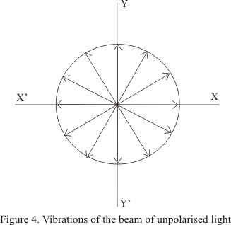
- As it can be seen from the figure that amplitude of vibrations are all equal
- When such a beam of unpolaroized light is incident on a Polaroid the emergent light is linearly polarized with vibrations in a particular directions
- The direction of vibrations of beam transmitted by the Polaroid depends on the orientation of the Polaroid
- Consider the vibrations in ordinary light when it is incident on the polaroid as shown in figure 3(a). Each vibrations can be resolved into two components, one in a direction parallel to a which is the direction of transmission of light through polaroid and the other direction m perpandicular to a as shown in the figure given below.
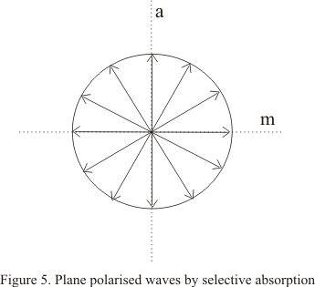
- Polaroids absorbs the light due to vibrations parallel to m , known as ordinary rays but allow light due to other vibration , known as extra ordinary rays, to pass through.
- So the plane polarised light due to vibrations in one plane is produced as shown in figure 3(a).
- The Polaroid absorbs the light vibration along a particular direction and the component at right angles to it is allowed to pass through the Polaroid.
- This selective absorption of light vibrations along a particular direction is also shown by certain natural crystals for example tourmaline crystal
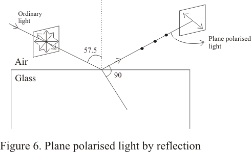
- This simple method of obtaining plane polarized light by reflection was discovered by malus in 1808
- We found that when a beam of light is reflected from the surface of a transparent medium like glass or water, the reflected light is partially polarized and degree of the polarization varies with angle of incidence
- The percentage of polarized light is greatest in reflected beam when light beam is incident on the transparent medium with an incident angle equal to the angle of polarization
- For ordinary glass with refractive index =1.52 ,angle of polarization is 57.50
- Figure below shows the polarization of light by reflection
- we can use a Polaroid as an analyzer to show that reflected light is plane polarized . we rather say that reflected light is partially plane polarized
- the examination of transmitted light shows the variation in intensity indicating that the light is partially polarized
- The vibrations of this plane polarized reflected light are found to be perpendicular to the plane of incidence and therefore ,the reflected light is said to be plane polarized in the plane of incidence
- when an unpolarized beam of light is allowed to pass through a medium containing gas or molecules it gets scattered and the beam scattered at 900 to the incident beam is plane polarized ( having vibrations in one plane). This phenomenon is called polarization by scattering
- The blue light we receive from sky is partially polarized ,although our eye can not distinguish it from an umpolaroized light but if we view it through a Polaroid which can be rotated we can clearly see it to be as partially polarized
- this is nothing but the sunlight that has been scattered when it encountered the molecules of the earth surface
8) Polarization and electric vector
- we know that a transverse EM wave contains both electric and magnetic field and electric field in light wave is perpendicular to the direction of propagation of light wave
- We generally define direction of light vibration to be that of the electric vector E
- For an ordinary unpolarised beam electric vector keeps changing its direction in random manner
- when light is allowed to pass through a Polaroid the emergent light is plane polarized with its electric vector vibrating in a particular direction
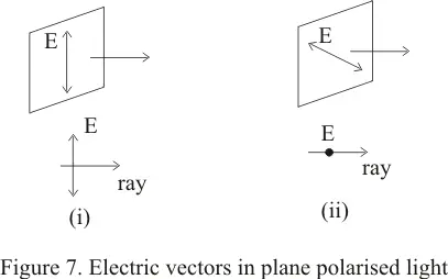
- The direction of vector of emergent beam depends on the orientation of the Polaroid and the plane of polarization is designed as the plane containing E-vector and light ray
- Figure below shows the plane polarized light due to i) a vertical E-vector ii) a horizontal E-vector
9)Law of Malus
- consider the figure given below in which an unpolarized light passes through a Polaroid P1 and then through Polaroid P2making an angle θ with y ax-s
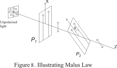
- After light propagating along x-direction passes through the Polaroid P1 ,the electric vector associated with the polarized light will vibrate only along y-axis
- Now if we allow this polarized beam to again pass through a polarized P2 making an angle θ with y-axis then if E0 is the amplitude of incident electric field on P2 then amplitude of wave emerging from P2 would be E0cosθ and hence intensity of emerging beam would be
I=I0cos2θ ---(4)
where I0 is the intensity of beam emerging from P2 when θ=0 - This equation (4) represents the law of malus
- Thus when a plane polarized light is incident on an analyzer ,the emerging light varies in accordance with the equation (4) where θ is the angle between the planes of transmission of the analyzer and the polarizer
- Brewster law is a simple relationship between angle of maximum polarization and the refractive index of the medium
- Brewster’s law is given by relationship
μ=tani --(5)
where i is the Polarizing angle
μis the index of refraction
It is clear from equation (5) that when light is incident at polarizing angle then reflected ray is at right angles to the reflected ray
No comments:
Post a Comment